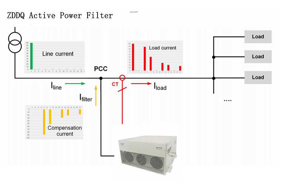
Harmonics and Active Power Filter
In recent years, the use of non-linear load is increasing day by day. Non-linear loads such as traditional diode/ thyristor rectifiers with inductive load generate harmonic and reactive current, which leads to poor power factor, low energy efficiency, and harmful disturbance to other appliances. Also, in recent years, the large-scale use of the power electronic equipment has led to an increase of harmonics in the power system. Harmonics also affects on the performance of distribution transformer. It increases power loss due to skin effect and proximity effect. Current harmonics are one of the most common causes of these problems and are usually resolved by using Active Power Filter (APF). By the implementation of a shunt active power filter on the secondary side of the transformer, the harmonics can be compensated which is produced by non-linear load. Finally, by the implementation of this concept the efficiency of the transformer, losses of the transformer, overheating of the conductor due to skin effect, power quality, etc. can be improved.
Innovative 3 Level topology of ZDDQ Active Power Filter
Current Transformer Installation
For accurate sensing of the load it is important that the load sensing current transformers are properly installed.
Warning!
|
Only qualified electricians should carry out all electrical installation and maintenance work on the Active Power Filter. Failure to follow standard safety procedures may result in death or serious injury. Disconnect all sources of power to the drive and APF before working on the equipment. Do not attempt any work on a powered APF. Also, check for zero voltage between all phases of the input and output lines. Operating current transformers with the secondary winding open can result in a high voltage across the secondary terminals which may be dangerous to personnel or equipment. |
The exact CT placement is dependent on ZDDQ APF’s configuration and size. Please contactwithus. info@zddqelectric.com
The CT must be orientated properly during installation. The orientation is specified in the drawings with an arrow indicating the direction or polarity of the CT. Most CT manufacturers will indicate orientation with a label indicating H1 on one side of the CT or a dot. There can also be a label indicating H2 and/or an arrow on the CT. The H1 side of the CT should always be closest to the power source. If the CT has an orientation arrow, it should point from the source towards the load. See the installation instructions for the specific CTs being installed.

Scan to WhatsApp:
